The drawing controls consists of a drawing editor that supports polygons, lines, shapes and text. This tool allows you to create and move graphics in the Main Display window. Drawing and selecting in 3D can be difficult and sometimes it is best to be in the main overhead view. This feature can be found in the Main Display window in the Display->Draw Freely menu.
The Drawing Control window consists of three tabs: Controls, Style, and Shapes.
The Controls tab is used to draw features in the Main Display window:
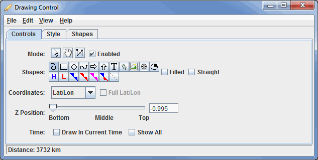
Image 1: Controls Tab of the Drawing Control Dialog
- Mode - There are three editing modes, select, move and reshape:
-
 Select - Selects one or more drawing objects. To select multiples press the control key. The selected objects will be shown with small magenta rectangles. Once selected, you can bring up the object's property editor by pressing Ctrl+P. You can also delete the selected objects by pressing Ctrl+X. You can select all of the objects by pressing Ctrl+A.
 -
 Move - Moves an object.
 -
 Reshape - Moves one of the points that define the location of an object.
 - Enabled - Turns on/off the ability to use the modes. This makes it easy to modify other objects that may be in the Main Display window without moving the position of your shapes.
- Shapes - Represents the shapes to create in the Main Display window:
 Create a polygon - Creates a smooth polygon.
 Create a rectangle - Creates a rectangle.
 Create a diamond - Creates a diamond.
 Create an arrow - Creates an arrow that can face in any direction.
 Create a horizontal arrow - Creates an arrow in the horizontal direction.
 Create a vertical arrow - Creates an arrow in the vertical direction.
-
 Create text - Opens a Text entry window, where you can type in text or HTML. Click OK when done, and the text will appear in the Main Display window.
 -
 Create waypoint - Opens a Text entry window, where you can type in text or HTML. Click OK when done, and the text will appear in the Main Display window along with a marker to represent the exact location where you clicked in the Main Display window.
 -
 Create image - Places a saved image or an image from an HTML address on the Main Display window. Select an image file from the file chooser.
 -
 Create quicktime movie - Places a movie on the Main Display window. Select the movie from the file chooser.
 -
 Create a symbol - Places a (+) symbol on the display.
  Create high pressure symbol - Adds a high pressure symbol to the Main Display window with a user-specified pressure.
 Create low pressure symbol - Adds a low pressure symbol to the Main Display window with a user-specified pressure.
 Create a cold front - Adds a cold front to the display.
 Create a warm front - Adds a warm front to the display.
 Create an occluded front - Adds an occluded front to the display.
 Create a stationary front - Adds a stationary front to the display.
 Create a trough - Adds a trough to the display.
- Filled - Fills in the outline of a shape.
- Straight - Creates straight lines when drawing freely.
- While the icon buttons only allow you to draw 5 different front types, there are 20+ front types to choose from in the Properties dialog for the shape.
- Coordinates - Draws in four different coordinate systems:
- X/Y/Z - Draws in the 3D box coordinate space. Re-projections will not effect the shape.
- X/Y - Draws in the 3D box coordinate space, fixing the Z position. Re-projections will not effect the shape.
- Lat/Lon/Alt - Defines the points of the shapes by Latitude/Longitude/Altitude. When you reproject the display the shape will also be reprojected.
- Lat/Lon - Defines the points of shapes by Latitude/Longitude, but the Z position is fixed using the Z Position slider. When you reproject the display the shape will also be reprojected.
- Z Position - Changes the vertical position of the features with respect to other variables being displayed in the main display window. You can change this with the slider, or by entering a value in the box and pressing Return.
- Time - Determines the visibility of your drawing items as you progress through time steps in a loop.
- Draw In Current Time - Draws the features only on the time step you are looking at. As you step through the animation, the features will not be visible in any subsequent time steps.
- Show All - Displays all of the features drawn at any time step, regardless of if Draw In Current Time was selected.
- A graphic can be shown at more than one time using the Property Editor. Select the object and press Ctrl+P to bring up the property editor. Select the times to be displayed in in the Times list (Shift+click or Ctrl+click to select multiples) and press Apply or Ok.
The Style tab controls the style that the drawings take in the Main Display window:
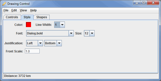
Image 2: Style Tab of the Drawing Control Dialog
These menu options apply to the shapes listed in the Controls tab, excluding the High/Low pressures/fronts. Once modifications have been made in this tab, they will be applied to the next shape you make in the Main Display window, without changing any shapes already created.
- Color - Represents the color of the shape/text in the display.
- Line Width - Represents the thickness of the shapes in the display.
- Font - Changes the font of the text in the display.
- Size - Changes the size of the text in the display.
- Justification - Changes the justification of the text.
- Front Scale - Changes the scale of the fronts.
The Shapes tab lists all of the graphical elements:
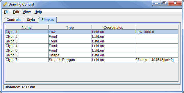
Image 3: Shapes Tab of the Drawing Control Dialog
This tab lists out the different shapes and information about them included in the Main Display window, selected from the Controls tab.
- Name - Lists the names of the shapes.
- Type - Represents the type of shape in the display.
- Coordinates - Lists the Coordinates selected in the Controls tab.
- Specifics - Lists specifics about some of the items, including pressure and area values.
Double clicking on an element in the Shapes tab will show its properties editor, which consists of two tabs: Properties and Points.
The Properties tab gives general information about each shape:
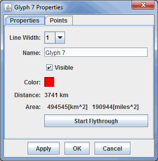
Image 4: Properties Tab of the Properties Dialog
This tab allows you to control many aspects of the individual shapes. Note: The different types of shapes will have different menu options.
- Line Width - Represents the thickness of the shapes being displayed.
- Name - Represents the name of the shape.
- Visible - Determines if the shape will be seen in the display.
- Color - Represents the color of the shape in the display.
- Distance - Represents the distance the object covers in the Main Display window.
- Area - Represents the area of a shape being displayed in the Main Display window.
- Pressure - Changes the pressure when your shape is a high or low pressure.
- Front Type - Changes the type of front displayed for the selected element.
- Flip the front orientation - Changes the display to represent the front traveling in the opposite direction.
- Scale - Changes the size of the front without changing its spatial extent.
- Times - Determines what times the shape will appear when you are displaying a loop of data.
 - Opens the Flythrough feature which allows you to interactively explore the feature.
The Points tab gives general information about each shape:
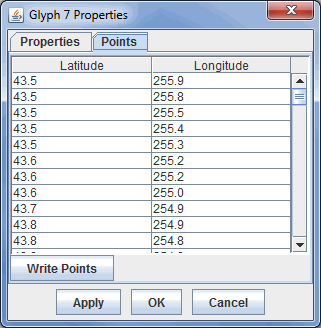
Image 5: Points Tab of the Properties Dialog
This tab lists out location coordinates of your shape. The points listed can be seen in the Main Display window, and are represented by the pink squares along the boundaries of the shape. These values can be changed by double clicking on a coordinate, and typing in a new value. Once you click on a different coordinate, and then press Apply or OK, the change will be made in the Main Display window.
- Latitude - Lists the latitude value at each point.
- Longitude - Lists the longitude value at each point.
-
 - Saves the list of points as a Comma-Separated Values (CSV) file (*.csv).
Many of the menu items seen utilizing this display are standard options that can be found in the Menus section of the Layer Controls Page. However, there are several options that are unique to this display.
The File menu has these unique options:
- Export Drawing - Exports the display in the IDV Drawing files (*.xgrf) format.
- Import Drawing - Imports the display in the IDV Drawing files (*.xgrf) format.
The Edit menu has these unique options:
- Remove All - Removes any drawings from the Main Display window without removing any other items.
- Apply Color to Selected - Changes the color of the selected item drawn in the Main Display window.
- Apply Z Position to Selected - Changes the Z position of the selected item drawn in the Main Display window.