[Table of Contents] [Go to Previous] [Go to Next]


Chapter 2

SDI Installation

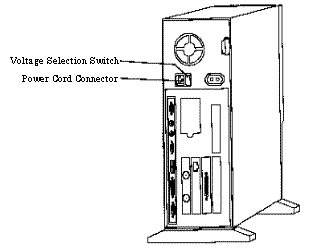
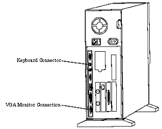
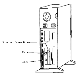
The SDI was initially built on an IBM® PC Server 310 computer; most later versions are built on IBM Netfinity server. Both computers run a Solaris operating system. SSEC's application software and custom hardware have been installed, and the complete SDI is tested prior to shipment. This reduces the installation to the following:

Perform the steps below to install your SDI.

Initial Inspection

    1. Remove the components from their shipping containers and inspect them for signs of shipping damage. Contact SSEC for further instructions if damage is discovered.

    Occasionally, SSEC's proprietary PCI interface card (shown in the picture below) becomes partially unseated during shipment. If this happens, you will get the following error message on your console when you power up the SDI.

    Therefore, as a precautionary measure, SSEC recommends that you remove the computer's outer case, reseat the interface card, and reinstall the outer case.

Location

    2. The SDI requires a standard PC environment that has access to the data and clock outputs from your satellite antenna chain. Since the SDI functions as an ADDE server, your location must also have a TCP/IP connection so that it can be accessed by ADDE clients.

Power Requirements

    3. The PC Server 310 runs on one of two switch selectable AC voltage ranges, 90-137 VAC or 180-265 VAC

The voltage-selection switch is located immediately to the right of the AC power cord connector, as shown in the drawing at the left. If your voltage is between 90 VAC and 137 VAC check to see that 115 is visible on the switch; if your voltage is between 180 VAC and 265 VAC, check to see that 230 is visible on the switch.

CAUTION

If you set the voltage switch to the wrong position, you might permanently damage your SDI when you turn it on.

Component Interconnections

    4. The SDI does not include or require a monitor or mouse. However, you may want to use a monitor to initially verify normal operation.

You can use any color or monochrome VGA monitor by connecting its data cable connector to the 15-pin D-connector located at the bottom-left corner of the computer, as shown in the drawing at the left.

The SDI is normally operated from a remote location by Telnet. Therefore, once normal operation is confirmed, there is no need for a monitor.

    5. Connect the keyboard to the connector indicated in the drawing above.

    The bit sync requirement is different for different satellite types. Refer to the Bit Sync Requirements description in the satellite-specific chapter for your ingestor for details.

Bit Sync requirements

Bit syncs provide clock and data outputs in either NRZ-L or NRZ-S format. The PCI Ingestor card in the SDI can decode either format via a selection jumper (JP11) on the PCI card. During initial installation, and/or after changing the bit sync, verify that the format selected on the PCI card matches the bit sync's output format. Refer to the picture below for the location of the jumper.With the PCI Ingestor board positioned as shown in the picture, pin 1 is "up".

The jumper configuration is defined as:

  • 1 - 2 = NRZ-S
  • 2 - 3 = NRZ-L

Remove the card from the PC before changing the jumper. If your SDI is an IBM Netfinity, first removing the bottom of the computer simplifies removal of the PCI Ingestor card.


Connecting External Inputs and Outputs

    6. Your antenna chain provides two 75-ohm outputs from its bit synchronizer. They should be labeled data and clock. If the cables are not labeled, you will identify and mark them during the completion of this step.

    Use an oscilloscope to verify that the output from each cable is between 2.0 and 2.75 volts peak-to-peak when terminated in a 75-ohm impedance. The line having a 50 percent duty cycle signal is the clock line. If it is not labeled, label it Clock and label the other line Data.


Connect the Data and Clock inputs shown in the drawing at the left. This completes the SDI installation process.

Connect the Ethernet cable to the connector indicated in the drawing at the left.

Continue with the chapter that contains the operating instructions for your data type.


IBM is a registered trademark of International Business Machines Corporation


[Table of Contents] [Go to Previous] [Go to Next]