The transect drawing controls are a version of the Drawing Controls that allows you to view, create, and modify the transect lines that are used in the Transect Views. This option can be found in the Main Display window under the Display->Draw Transect menu item or through the Transects menu in the Transect View.
This display control is a representation of the set of transects that are defined by the transect resource. Not only does it have its own state (that can be saved in a bundle, for example), but it also writes out any transects you may create or change into your local McIDAS-V state directory in a transects.xml file. This transects.xml file (if one is created) is carried over from session to session. Therefore, if you draw transects in one session and save the transects (via the File->Save or Automatically update transects items), the same transects will appear in subsequent sessions when you open the Transect Drawing Control widget.
In this control, there is only one shape that you can draw, a Transect Line. This control also shows a non-editable Transect Shape which displays the full transect line used by any Transect Views, called the "Active Transects". There are also a set of transect lines that are non-editable that are from the system transects property. For an active transect, if the Transect View that it represents has a max distance set then the transect will show this max distance as a rectangular box.
The Transect Drawing Control window consists of three tabs: Controls, Style, and Shapes.
The Controls tab allows for the user to draw features in the Main Display window:
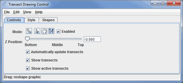
Image 1: Controls Tab of the Transect Drawing Control Properties Dialog
- Mode -
 Create a transect - Creates a transect in the Main Display window by left-clicking and dragging.
-
 Select - Allows you to select one or more transect drawings. To select multiples press the control key. The selected transects will be shown with small magenta rectangles. Once selected you can bring up the transect's property editor by pressing Ctrl+P. You can also delete the selected objects by pressing Ctrl+X. You can select all of the objects by pressing Ctrl+A.
 -
 Move or stretch graphic - Allows you to reposition a transect without stretching (changing the distance between the endpoints) it.
 -
 Stretch Graphic - Allows you to move one of the endpoints of a transect. The other endpoint will remain in its fixed location.
 - Enabled - Allows you to utilize the different mode options. If you are done creating/modifying transect lines, you can unselect this option to allow you to work in the Main Display window without creating/modifying any existing transect lines.
- Z Position - Allows you to define the Z-position of the transect line. This is the vertical positioning of the transect line in the Main Display window.
- Automatically update transects - Makes your most recently drawn transect line the active transect, and it will control the display if you are working with a Transect Display. This will also write out all transects (active and inactive) to a transects.xml file stored in your McIDAS-V directory.
- Show transects - Toggles the visibility of all transect lines drawn in the display, other than the active transect, which is controlled by the Show active transects item.
- Show active transects - Toggles the visibility of the active transects. Active transects are transects that are currently being utilized to create a display in a Transect Display. Active transects are drawn in the color green in the Main Display window.
The Style tab controls the appearance of the transect lines in the Main Display window:
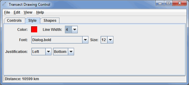
Image 2: Style Tab of the Transect Drawing Control Properties Dialog
These menu options apply to the shapes listed in the Controls tab. Once modifications have been made in this tab, they will be applied to the next transect you draw in the Main Display window, without changing any transects already created. Note that Font and Justification are not valid options for this control, since there is no text component in the Controls tab.
- Color - Sets the color of the transect in the display.
- Line Width - Sets the thickness of the transect drawn in the display.
The Shapes tab lists all of the graphical elements:
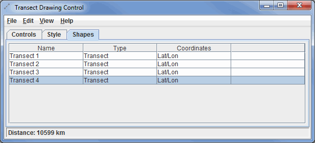
Image 3: Shapes Tab of the Transect Drawing Control Properties Dialog
- Name - Lists the names of the transects.
- Type - Lists the type of shape in the display. This will always be listed as 'Transect' because that is the only shape you can create from the Controls tab
- Coordinates - Lists the coordinates used to display the transect line.
Double-clicking on an element in the Shapes tab will show its properties editor, which consists of two tabs: Properties and Points.
The Properties tab gives general information about each transect:
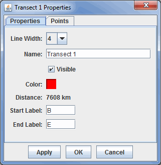
Image 4: Properties Tab of the Properties Dialog
- Line Width - Sets the thickness of the transect line.
- Name - Sets the name of the transect. This is the name that will be listed in the Name column of the Shapes tab of the Drawing Control window. Setting names of items can make it easier to keep multiple shapes organized, as opposed to the default of "Transect 1", "Transect 2", etc.
- Visible - Toggles the visibility of the transect line in the Main Display window. If this item is unchecked, it will not be visible in the Main Display, but the shape itself will not be deleted. Any transects that aren't visible will have '(hidden)' listed next to their names in the Shapes tab of the Transect Drawing Control window.
- Color - Sets the color of the transect line in the display.
- Distance - Lists the geographical distance the transect covers in the Main Display window. This cannot be changed here, and is listed for informative purposes only.
- Start Label - Sets the label at the beginning of your transect line in the Main Display window. The default value here is B, for Beginning.
- End Label - Sets the label at the end of your transect line in the Main Display window. The default value here is E, for Ending.
The Points tab gives general information about each shape:
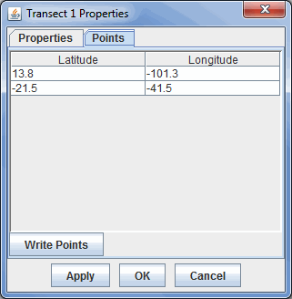
Image 5: Points Tab of the Properties Dialog
You can modify a latitude/longitude value here by double-clicking in one of the cells for latitude or longitude, entering a new value, clicking in another cell, and clicking Apply or OK. The new latitude/longitude values will be applied to the endpoints of your transect line in the Main Display window.
- Latitude/Longitude - Lists the latitude/longitude values of the starting and ending points of the transect line.
 - Allows you to save the list of points as a Comma-Separated Values (CSV) file (*.csv).
Many of the menu items seen utilizing this display are standard options that can be found in the Menus section of the Layer Controls page. However, there are several options that are unique to this display.
The File menu has these unique options:
- Save Transects - Allows you to save your transect display. This will save information about your transect lines currently displayed in the Main Display window to a transects.xml file stored in your McIDAS-V directory. This file contains information about transect line beginning and end points, color, and starting/ending labels.
- This transects.xml file is important when working with a Transect Display, as these are the transect lines that are listed out under the Transects menu item in the Main Display window. This makes it easy to switch between different transect lines for your transect display without having to re-draw lines.
- Save - Allows you to save the transect display as a bundle or a favorite.
The Edit menu has these unique options:
- Remove All - Removes all transects from the Main Display window without removing any other items. Note, if you have the Automatically update transects option turned on, this will delete all transects from your transects.xml file.
- Apply Color to Selected - Changes the color of the selected transect drawn in the Main Display window. After an item is drawn, if you want to change its color in the Main Display, you can make the item active with the Select mode, change the Color in the Style tab of the Drawing Control window, and use the Apply Color to Selected menu item to change the color of the item to the new color you selected.
- Apply Z Position to Selected - Applies a modified Z-position (height) to the selected transect drawn in the Main Display window. After an item is drawn, if you want to change its vertical positioning in the Main Display, you can make the item active with the Select mode, move the Z-Position slier in the Controls tab of the Drawing Controls to your new desired position, and use the Apply Z Position to Selected menu item to move the item to the new Z-position.