Parameter Defaults Editor
The Parameter Defaults Editor is opened through the Tools
menu in the Main Display window with Tools->Parameters->Defaults and
allows for the specification of default color tables, ranges, units, and
contouring values for different parameters:
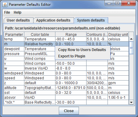
 Image 1: Parameter Defaults Editor
Properties
- Parameter - Represents the name of the parameter. The double down arrows allow you to change the parameter to one of a loaded data source, or a predefined alias.
- Color Table - Shows the active color table and the associated high and low data values in the units of the display.
- Range - Represents the range that the color bar will cover, from low to high.
- Contours - Represents the spacing (difference in value) between contours.
- Display Unit - Represents the unit used to display the parameter.
This feature lets you preset conventional color and contouring choices, and lets
you override system defaults.
There are two sets of defaults: user defaults in the User defaults tab,
and system defaults supplied with McIDAS-V in the System defaults tab.
While the actual system defaults cannot be modified, anything you modify will be transferred to the User defaults tab. When you do this
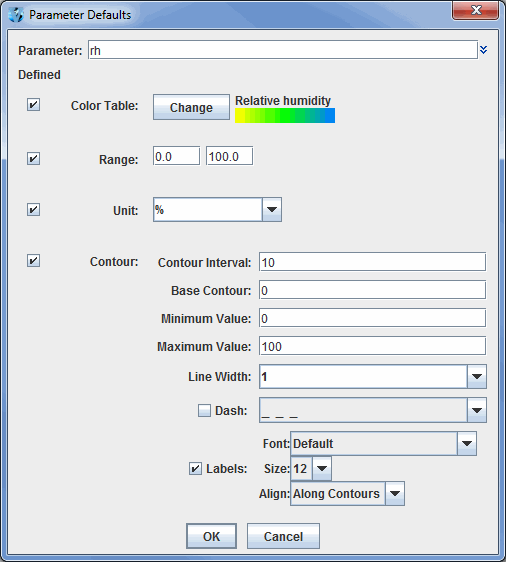
the Parameter Defaults window allows you to select what properties
you want to define:
 Image 2: Parameter Defaults Properties
Simply check or uncheck the Defined buttons and define
the settings as desired. From the user defined table you can also right click
on a row to add a new row, edit the settings for the row or delete the row.
The parameter names are given in regular expression syntax to help match with
actual data names. Plain text is matched exactly. The string dot star, ".*",
means "any text here." The ^ means "begin with the following text exactly".
Properties
- Parameter - Represents the name of the parameter. The double down arrows allow you to change the parameter to one of a loaded data source, or a predefined alias.
- Color Table - Shows the active color table and the associated high and low data values in the units of the display. As the mouse pointer is moved over the color bar, the value at a particular color is shown. Right click on the color bar or click on the button that displays the name of the Color Table to make modifications to the color bar. This allows you to open the Color Table Editor, change the range, select other color tables, etc.
- Range - Represents the range that the color bar will cover, from low to high.
- Unit - Represents the unit used to display the parameter.
- Contour Interval - Represents the spacing (difference in value) between contours. There are four ways to specify the contour interval.
- 1. Specify a single value to denote a regular interval between contours.
- 2. Specify irregular contour intervals with a semi-colon separated list of values. For example:
- 5400;5460;5800. This would only show contours at 5400, 5460, and 5800.
- 3. Specify different contour intervals for different ranges in the following format:
- cint1/min1/max1;cint2/min2/max2;...;cintn/minn/maxn
- For example, with geopotential heights: 30/0/4200;60/4200/8600;120/8600/24000
would draw contours at 30gpm between 0 and 4200, 60gpm between 4200 and 8600, and 120gpm between 8600 and 24000
- 4. Specify one individual contour by setting the interval, min, and max as the same value. For example:
- 5400/5400/5400. This would only show the 5400 line.
- Base Contour - Represents the value on which all contours are based. All contours will be integer multiples of the contour interval from the base value. For example, with a base value of 0 and a contour interval of 3 contours would be created at ... -6, -3, 0, 3, 6... A base of 1 with that interval would create contours at ... -5, -2, 1, 4, 7... The base value does not have to be the lowest contour level on a plot, or inside the range of values plotted; it is only a computational reference point. The base contour value is also used for controlling which lines are dashed.
- Minimum Value - Represents the limit below which no contour lines are shown. The minimum value may be larger than the base value, so that the base value may never appear on a plot.
- Maximum Value - Represents the upper limit above which no contour lines are shown. The minimum and maximum values do not need to match contour line values; they are only limits.
- Line Width - Represents the line width (in pixels) of the contour lines and labels.
- Dash - Dashes contour values less than the base value. If the base is set higher than maximum value, then all lines are dashed. Use the pulldown menu to select the dash pattern to use.
- Labels - Displays contour labels on the image.
- Labels: Font - Represents the font style of the contour labels.
- Labels: Size - Represents the font size of the contour labels.
- Labels: Align - Represents the way contour labels will be written on the contours. Along Contours means the labels will be written along contours, and while they will not be written upside down, there is a chance they will be written at an angle depending on the layout of the contours. Horizontal means the contour labels will be written on the contour, but it will be written in the horizontal and not on an angle.
Menus
The File menu has these unique items:
- New Row - Opens a Parameter Defaults window, which allows you to select what properties
you want to define.
- Open - Allows you to open an eXtensible Markup Language (XML) file (*.xml).
- Import - Allows you to import an eXtensible Markup Language (XML) file (*.xml).
- Export to File - Allows you to save your Parameter as an eXtensible Markup Language (XML) file (*.xml).
- Export to Plugin - Opens the Plugin Creator window with all of your aliases loaded in.
- Export Selected to Plugin - Opens the Plugin Creator window with your selected aliases loaded in.
- Close - Closes the Parameter Defaults Editor window.


