Overview
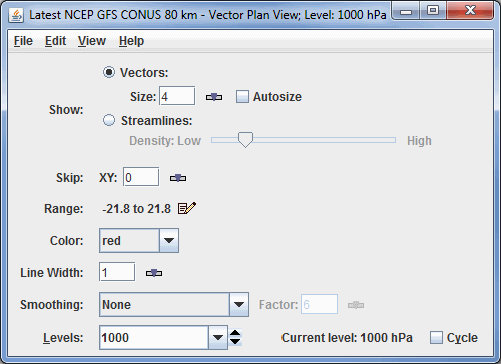
The Flow Plan View Controls are used to control plan (horizontal) displays (flow vectors, wind barbs, streamlines) of vector based data (e.g., wind components). They are similar to the Plan View controls.
The five types of Flow Displays are Vector Plan View, Streamline Plan View, 3D Vector Plan View, Wind Barb Plan View, Vector Cross Section, and Wind Barb Cross Section:

Image 1: Properties Dialog for the Flow Display Controls
Properties
- Show - Switches between displaying Vectors or Wind Barbs and Streamlines.
- Vector Size - Displays vectors in the Main Display window. Size changes the length of the vectors.
The Size box is an editable box where you can enter a new size and press return,
or use the slider (
 ) to
change the value. When the Autosize checkbox is checked, the size of the vectors will decrease proportionally as you zoom in or out of the image. When unchecked, the vectors will remain the same size regardless of zoom level.
 - Streamline Density - Displays streamlines in the Main Display window. Density changes the density of the streamlines on the display.
- Skip - Defines the number of grid points that are skipped to avoid cluttering. A skip interval of 0 mean show all vectors, 1 means skip every other vector, 2 means show every third vector, etc. This is also an editable box, enter a new skip interval and press return.
- Range - Lists the current range of data for sizing the vectors. Click on the Edit (
 ) icon
to change the range. This is an option with the Vector Plan View and Streamline Plan View displays.
 - Color - Changes the color of the streamlines and the vectors in the display.
- Line Width - Sets the line width in the display. Click on the
 or
put in a value and hit enter to change the value.
 - Smoothing - Smooths the grid. There are seven types of smoothing: None, 5-point, 9-point, Gaussian Weighted, Cressman Weighted, Circular Aperture, and Rectangular Aperture. The amount of smoothness can be set for all except the 5 and 9-point smoothers. The higher the amount, the smoother the grid. For the Cressman, Circular and Rectangular aperture smoothing types, the smoothing factor is the radius in grid spacing units.
- Levels - Lists the native grid levels. Click on one level value to reset the plan to that level. The plan level in use is shown in the data's native altitude units. The Levels box is editable. Click in the box, enter a value and hit return to set your own value. Additionally, you can click on the arrows to the right of the Levels box to switch levels, or click on the Cycle checkbox to animate vertically through all available levels.
- Selector Position - Determines the vertical positioning of the Selector line with respect to other variables displayed in the Main Display window. This is an option with the Vector Cross Section and Wind Barb Cross Section displays.
- Vertical Scale - Changes the vertical axis of the chart in the Display tab of the Layer Controls tab of the Data Explorer.
- Autoscale - Scales the Y-Axis automatically to the data range along the selector line in the display.
Menus
Many of the menu items seen utilizing this display are standard options that can be found in the Menus section of the Layer Controls Page. However, there are some options that are unique to this display.
The Edit menu has these unique options:
- Levels - Represents the level where the data is displayed. This is an option in the Contour Plan View, the Color Shaded Plan View, and the Wind Barb Plan View.
- Color - Changes the color of the streamlines, vectors, or wind barbs in the display.
The View menu has this unique option:
- Use Grid Projection - Re-centers the display and resets the zoom level back to the display's initial settings without changing any other preferences you have modified. This is an option in both the Contour Plan View, the Color Shaded Plan View and the Wind Barb Plan View.