Laser Replacement Procedure
Tools and Equipment Required
- Replacement laser
- Anti-static wrist strap
- Phillips screw driver
- Pliers for tensioning the laser brackets (optional)
- Small bags/cups for loose screws
- Tape for stabilizing laser power supply
- Lens tissue + 95% ethanol, for laser cleaning, if necessary
Precaution
- This procedure is for replacing lasers in Standard Range AERI instruments that do not have hygroscopic (humidity sensitive) optics. For Extended Range (ER) AERIs, see the alternate Laser Replacement Procedure with Purge
- The laser and other electronics inside the AERI are static sensitive. Wear a grounded anti-static wrist strap when handling the laser and components inside the AERI.
Procedure
- Power OFF the AERI instrument (either using the power bar in the back-end, or by unplugging AC power, or using the iBootBar).
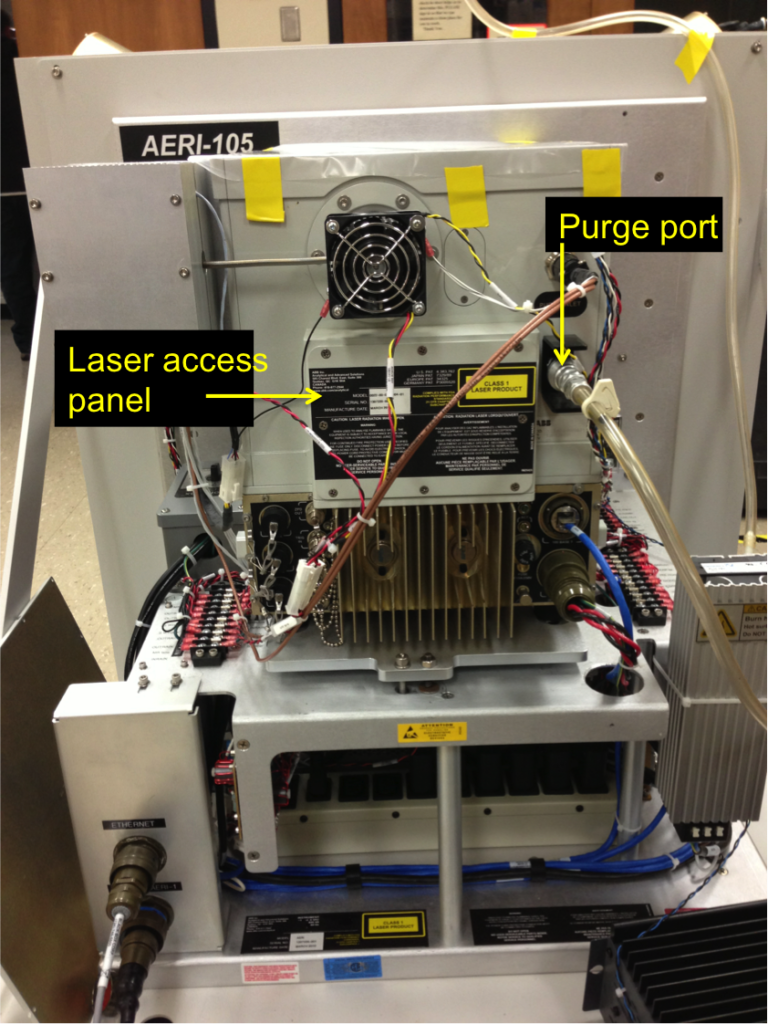
- Remove the laser access panel in the middle of the back of the instrument – it’s held on by 8 Phillips head screws (see Fig. 2).
- Wear a grounded anti-static wrist strap when handling the laser and components inside the AERI.
- The laser inside the access panel may still have charge on it and needs to be discharged. Using a screw driver with an isolated handle, discharge the laser tube by making short-circuit between the laser terminal (red wire) and the metal case of the instrument: Touch the screwdriver tip to the terminal, and the side to the instrument case. Usually a small spark will be visible at the terminal (see Figs. 3, 6).
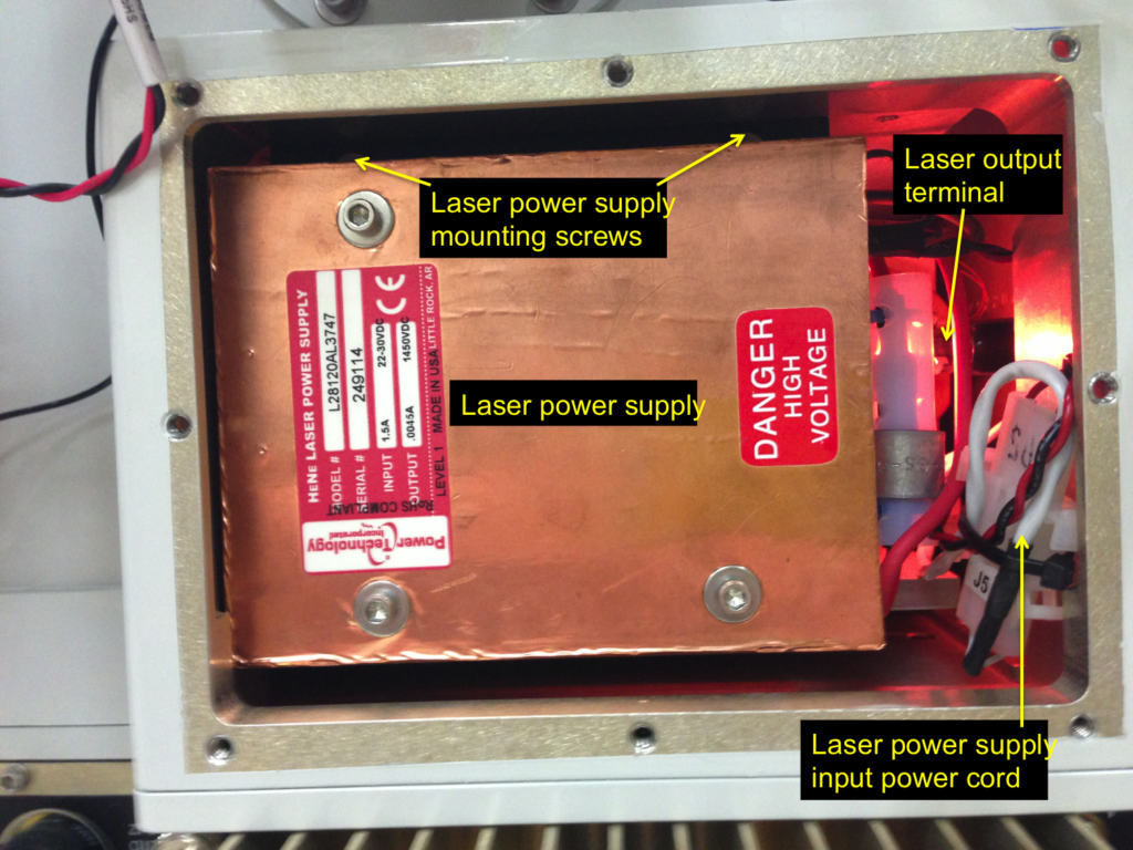
- Unscrew the laser power supply: it’s secured with two Phillips head screws located above the power supply (see Fig. 3).
- Remove the laser power supply, being careful not to strain the wires going to the laser. The power supply needs to be secured near the instrument. One option is to hold the power supply against the AERI case using tape (see Fig. 4).
- Confirm that that laser has been discharged, by repeating step #4, now that the laser terminal is more clearly visible and accessible.
- Unscrew the two screws that hold the straps that keep the laser tube and ballast resistor (inside white plastic tube, on red wire) in place (see Figs 5, 6).
- Carefully remove the laser tube from the interferometer. It’s easiest to remove the red side first. Carefully remove the red and black leads from the terminals, taking care not to strain the solder joints on the wires.
- Note the serial number of the old laser (e.g. 1234AB), wrap up the tube, and label with the date removed and the site.
- Inspect the new laser. Remove the small black cap from the lasing surface if needed (and cap the old laser). The lasing surface should be clean. Clean with 95% ethanol if necessary. Note the serial number of the new laser begin installed.
- Attach the red and black leads to the laser terminals. Make sure the connectors make a good connection with the terminals. The connector on the black lead in particular may need to be squeezed to ensure good contact with the terminal. Take care not to strain the solder joints on the wires.
- Carefully install the laser tube onto the v-groove mount. The pin on the right ring must slide into the alignment hole on the back of the right mount.
- Secure the two straps around the laser tube and attach with the two screws. The ballast resistor assembly also gets secured with the right screw. The resistor assembly should be oriented with the red wire going to laser coming out from the top, and should be completely vertical (see Figs. 5, 6). Snug the straps against the laser tube, either by gently pushing down from above, or by gripping the bottom with tweezers/pliers and pulling down gently. Tighten the two screws holding the straps.
- Ensure that the laser tube is secure. Gently grip the glass laser tube, and test if it can be moved with respect to its bracket. If the laser tube can be moved, then the strap holding it down needs to be re-tightened: loosen the screws and retighten the straps, as described in the step above.
- Take a photo of the configuration.
- Re-install the laser power supply. The two Philips head screws have limited access, so it is best to use a captive screwdriver, or simply use electrical tape to tape the head of the Philips screw and the shaft of the screwdriver, then remove once the screw has caught. Be careful not to catch and squeeze the red and black laser wires behind the power supply. It is best to get both screws of the laser power supply loosely into their thread, then route the laser wires so that they are free, then fully tighten the laser power supply screws. Neatly pack the laser power supply input power cord on the right side.
- Re-install the laser access panel with the 8 Phillips screws.
- Power ON the instrument.
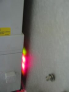
- Confirm the laser alignment: Observe the startup sequence of LEDs (visible as a reflection on the back wall on the right side of the instrument) (see Fig. 8). After the startup sequence (~1 minute), the top green light should be solid, and the bottom orange light should be blinking rapidly.
- If the bottom orange light is blinking then the laser is operating correctly and the replacement is complete. The instrument can be returned to service.
- If the bottom orange light is not blinking, or if a red light is solid or blinking, then the laser detector may not be aligned correctly. Power OFF the AERI promptly, particularly if the interferometer is making abnormal sounds, and consult the mentor team on further action.
Figure 2. Interferometer back-end
Figure 3. Laser access port
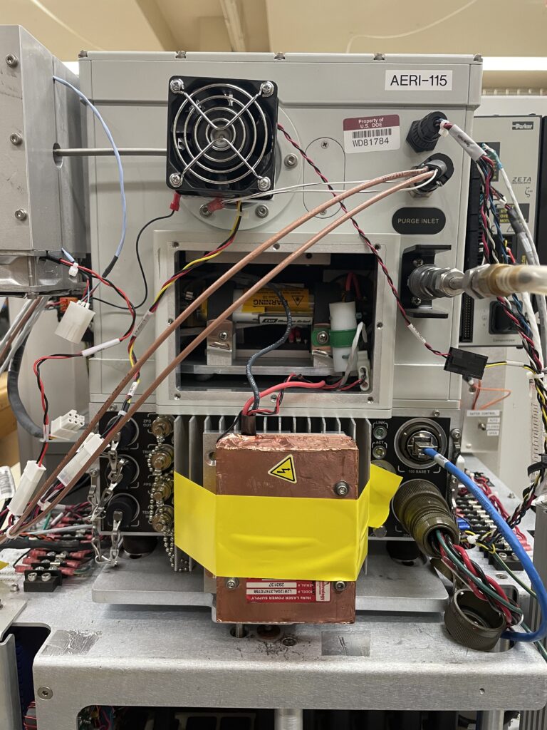
Figure 4. Power supply removed
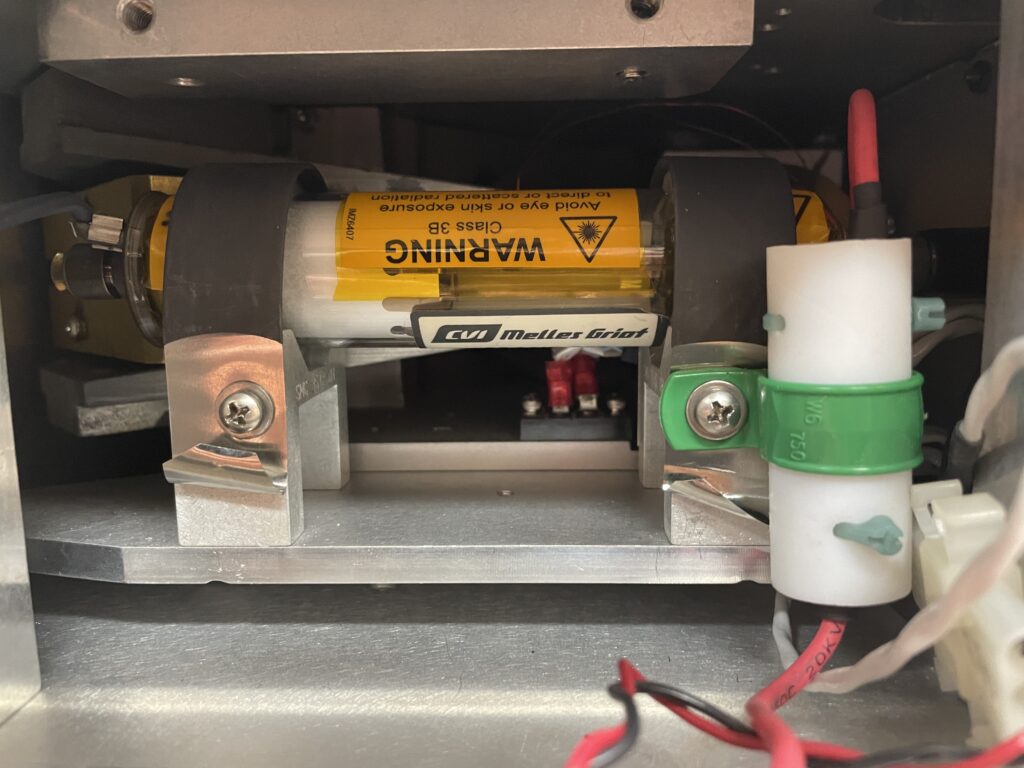
Figure 5. Laser tube secured with straps. Ballast resistor assembly is on the right
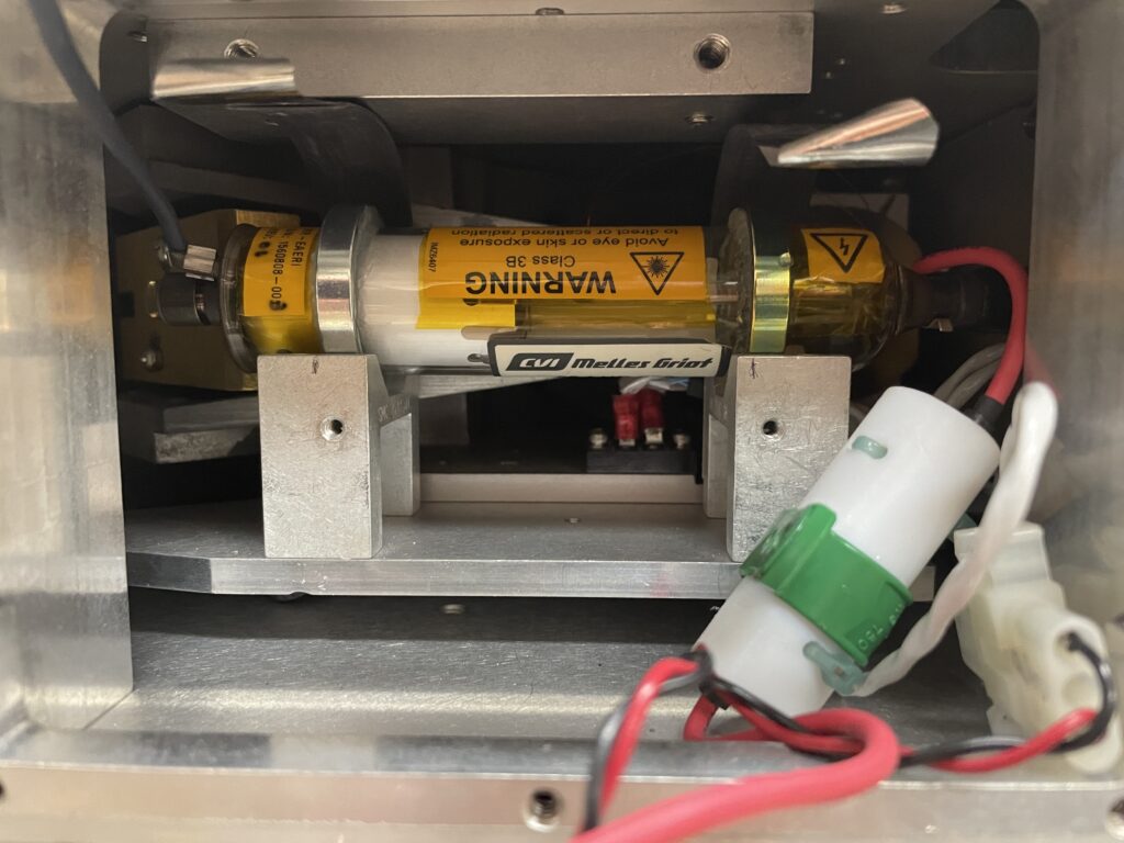
Figure 6. Laser tube, with straps removed
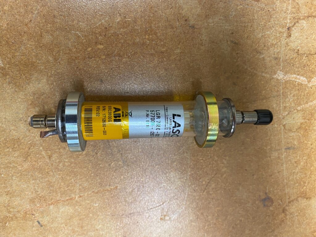
Figure 7. AERI metrology laser
Figure 8. Interferometer status lights during startup

