AERI Front-end Enclosure Removal and Installation Procedure
Tools and Equipment Required
- Large phillips screwdriver
- Ball driver set
Precaution
- At least two people are needed to safely remove/install the AERI front-end enclosure
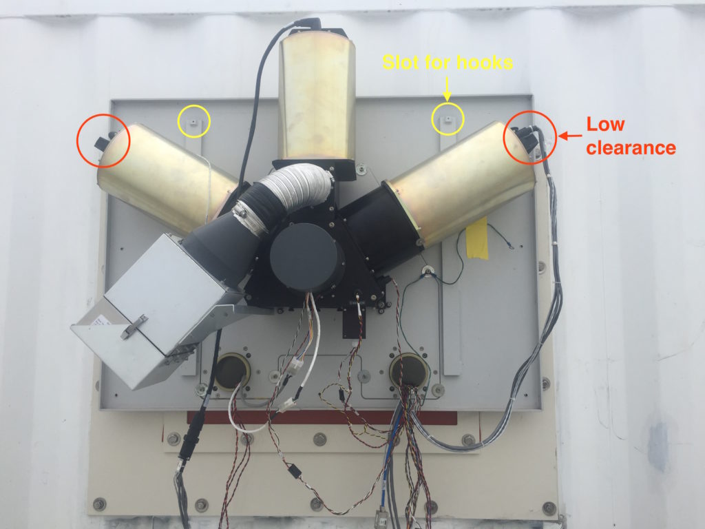
- There is very little clearance between the blackbody cables and the sides of the enclosure – take care to not damage the cables
Removal Procedure
- Ensure that the instrument is powered OFF.
- Remove the front-end panel using the 6 captive phillips head screws.
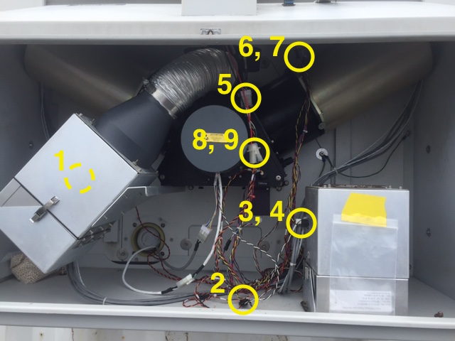
- Disconnect all cables between the AERI back-end and the front-end enclosure. These are listed in the table below and shown in Fig. 1.
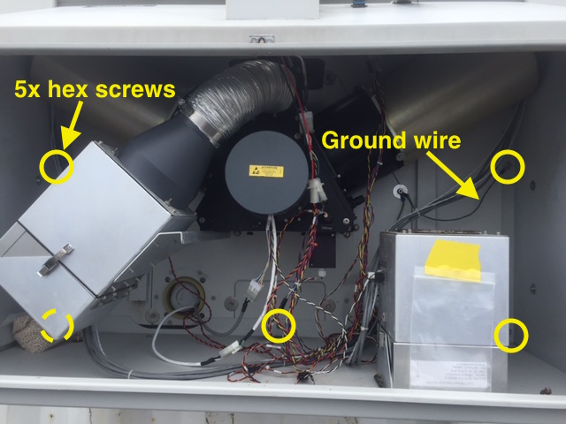
- Unscrew the five #10 socket head screws holding the front-end enclosure to the back plate. Note the attached ground wire (Fig. 2).
- Remove the front-end enclosure
- Two people are needed, one on each side
- First lift the enclosure so that the hooks on the enclosure clear the slots in the back plate
- Rotate the enclosure so that it clears the blackbody cable on one side
- Next rotate the other way to clear the blackbody cable on the other side
- Fully remove the enclosure, ensuring that no cables remain connected
- Set down and store the enclosure safely, so that the hatch, rain and sun sensor are not damaged.
Installation Procedure
- Ensure that the instrument is powered OFF.
- Ensure that the blackbody connectors are in place, and that the sky view aperture is clear.
- Connect the interior fan power cable (FAN IN). This is a lot easier to do before the enclosure is installed
- Physically install the front-end enclosure
- At least two people are needed, one on each side. A third person (optional) can help ensure that all the cables are clear.
- Lift the enclosure near the AERI front-end and place the loose wires inside the enclosure
- Rotate the enclosure in place around only one of the blackbodies on one side.
- Next rotate the enclosure the other way to place it around the other blackbody. The clearance between the blackbody cables and the enclosure is very low, and slight pressure needs to be applied to put the enclosure in place
- Ensure that the loose cables from the back end are all inside the enclosure. Ensure that the two blackbody cables are inside the enclosure
- Lower the hooks of the enclosure into the slots on the back plate. Verify again that all cables are clear and inside the enclosure
- Attach the enclosure with the five #10 socket head screws. Reattach the ground wire (Fig. 2).
- Reconnect the cables between the front-end enclosure and the AERI back-end. These are listed in the table below and shown in Fig. 1.
- Replace the front-end panel using the 6 captive phillips head screws.
Table 1. Connections between AERI back-end and front-end enclosure.
| Name | Label | Connector | Notes | |
|---|---|---|---|---|
| 1 | Interior fan power | FAN IN | Square 4-pin | Located on the back-side of the fan |
| 2 | Outside air temp | OUT AIR | Flat 4-pin | |
| 3 | Exterior fan power | FAN OUT | Square 4-pin | |
| 4 | Exterior fan air flow sensor | AirFlow | Flat 5-pin | |
| 5 | Interior rain sensor | INRAIN | Rectangular 10-pin | |
| 6 | Exterior rain sensor | OUTRAIN | Rectangular 10-pin | |
| 7 | Sun sensor | OUT SUN | 2-pin | |
| 8 | Hatch power | TRAP M | Square 4-pin | |
| 9 | Hatch switch | TRAP SW | Rectangular 6-pin |
Figure 1. AERI front-end with panel removed. Nine connections between the back-end and the front-end enclosure are shown.
Figure 2. AERI front-end with panel removed. Five hex-head screws attaching the enclosure to the back panel are shown, along with the ground wire.
Figure 3. AERI front-end with enclosure removed. Area of low clearance due to blackbody cables indicated in red. Slots for hooks on front-end enclosure shown in yellow.


